After having a set of NRF24L01+'s and SI24 based similar transceivers sitting around for a while, I figured I'd start working on something with them. If you tried to do any ebay shopping for the nrf24's you'll most like find the si24 are the ones you get at a super deal(10 for 10). So after working on a simple proof of concept with a completely different setup(arduino based as it has a fast turnaround), I started playing around with the SI24s for the MSP version of the project.
So if you are going to play around with these, it's good to get at least 3 so you can see how fun they are with the multi pipe setup. As mentioned I grabbed a 10 pack which is also a good starting point for having a full build project, and a test project.
The library I used is from Spirils and is located here. He keeps it up to date and it works great. For the tests and setup, I've been using the G2452 as I had 4 lying about from the launchpad kits that I had.
I suggest reading the doc for this lib as it's quite useful and can clear up most questions.
To be clear though I did run into some spots where I wasn't quite sure if I was doing something correct, but found enough info and when needing clarficiation, finding Spirilis on IRC@freenode.
Helpful hints
One of the first functions that you should use to troubeshoot is the msprf24_is_alive() function. Immediately you will know by the return value if your device is working or not.
If you are spamming your receiver, make sure you are handling all of the data that comes in before you put it to sleep.
Sunday, August 23, 2015

NRF24L01+ MSP430 adapter board
Finally got some work done on my adapter board for the NRF24L01+ or the SI24L(whatever the chinese knockoff is). The board was based on the datalogger board that I had created. I removed the memory chip and added the pinout header for the NRF module. I opted to forgo a crystal, and left the pins unused.

Will add a link to the source code and board link on OSH park.
Tuesday, January 22, 2013
Yes I'm still working on stuff....
Jruby, why you so silly.....
The Problem: jruby doesn't want to run my .rb files, instead it complains about the lack of a path in JAVA_HOME.
The full error: "Cannot locate Java installation, specified by JAVA_HOME:"
Observation:
- jruby -v seems to work fine...
- jruby myfile.rb doesn't work(fails in IDE as well).
- jruby --help works...hmmm...?
- jruby -v myfile.rb works....really??
So do I need to pass a param to get it to work? Yup!
I don't want to pass something silly like -v every time I want to run a ruby script so the next best thing is to force the version by using --1.9
So "jruby --1.9 myfile.rb" works.
Annoying, yes, but solves at least one of my problems....next, get serialport gem working on the windows side if possible...
I'm still fairly new to using jruby, so maybe this is something that I'm just not familiar with...
EDIT:
After further investigating changing the following values appears to resolve most of the other issues I was running into.
Remove JAVA_HOME env variable completely
set JAVACMD to use c:\jruby-1.7.2\jre\bin\java.exe
EDIT:
After further investigating changing the following values appears to resolve most of the other issues I was running into.
Remove JAVA_HOME env variable completely
set JAVACMD to use c:\jruby-1.7.2\jre\bin\java.exe
Wednesday, October 31, 2012
Wand Buildout
The assembly of the wand became somewhat tricky with the wiring and the electronics package and the container.
The wand handle base was where all of the wires came out. Im glad I had some extra wire but it became a problem fitting into the pill bottle.
 The electronics package itself was a bit tricky to construct with the limited confines of the pill bottle, but in the end, it was able to squeeze inside the bottle. The only thing is that due to the extra wiring, it is pushed out of the back and sticks out. Solution, add a bigger bottle to the end.
 This is the bottom side showing the accelerometer. Everything is hardwired so I'll have to desolder it when I'm done.

The top view showing the transistors and power side of the module. Building this out was well...a test of patience...
 And finally, the end product. The hand leaves a bit to be desired....but it works. The paint job needs some work, but hey, this could be used for something else later on.


The wand handle base was where all of the wires came out. Im glad I had some extra wire but it became a problem fitting into the pill bottle.
The top view showing the transistors and power side of the module. Building this out was well...a test of patience...
Monday, October 22, 2012
Magic wand continued
Wand handle
This is where the electronics will be stuffed. This just consists of(fairly obvious) a wine cork drilled out through the center and a pill bottle. I made sure to get the pipe through the cork and stuff the end into the pill bottle just to give it some extra stability. It feels pretty solid as it is, and all parts are pretty snug. I'll most likely use some silicone glue and some clay mache to give the wand a wooden texture, then paint it as such.
The current parts list is the following:
- MSP430G2231
- MCP1702 3.3v vreg
- MMA7361 3 axis Accelerometer
- Lipo battery 150mah
- support parts: resistors, caps, switches and wire.

This is the electronics setup. Im using the button on LP board to test the single button that'll be connected to the chip. The only thing I haven't tested with just yet is the vreg, though I've used them before, so it shouldn't be that much of an issue. Wiring it all up is my only concern...

Sunday, October 7, 2012
So we have this thing at work....and I decided to participate...Harry Potter theme....and I wanted to make something cool...so I decided to make a wand powered by a MSP430 proc....
 ...and an accelerometer...
 hmmmm...I think it may come out pretty cool.
This is just a mockup of the wand with the center glow rod(in blue). The tip end still needs some work, but this is what the tricolor LED will be used for. More to come as I work on it...

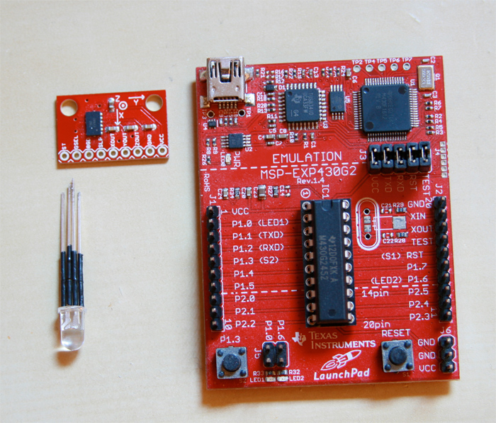
This is just a mockup of the wand with the center glow rod(in blue). The tip end still needs some work, but this is what the tricolor LED will be used for. More to come as I work on it...
Saturday, September 8, 2012
Powerboard V1.3
This is the third iteration of the powerboard(1.3) that I've been using for work with solar cells. It was meant to be a smart version using a 2211 to monitor the voltage levels via comparator. The other part of this project board was to also test 2 things. First, printing of the board to get an idea of the size and test the layout. Second was to test a smt crystal. Both of these objectives were reached, but...

Unfortunately there are several issues with the board, most of which can be worked around, but with the loss of designed functionality. I will admit, this is one one poor design and will need to be resolved. With this, I can actually add some new hw functionality, though I'll be doing a bit more checking next time.
Monday, August 13, 2012
as I don't have the exact times, I believe the flat lines around the 25-35 level are from an external lamp or from the monitor. I haven't not confirmed it yet. I should hopefully have 2 channels recording this week and can start looking at light levels and temp readings throughout the days. first a simple 1 day test, then a week long test.

Monday, July 30, 2012
Wired up.
Logger wired up with the addon board. This was a quick setup with a button board, sensor board(cds connected) and just a third wired servo wire connector. I also decided to use jst power leads for the battery adapter harness(was tired of the long leads for the original connector). This is connected to an xbee for transferring the data wirelessly, and of course an LP for the programming.
 The space taken by the program is currently just under 3k and I have a bit more to add...This is a bit of a concern and I'm considering using a 2453 for the last board as it'll double the amount of program space I have available. I'd prefer not to do this as I think the 4k limit I initially wanted to keep the prog within is still within reach.
Currently the updated code adds a simple header writer function that I've implemented on the single channel recording and another test mode that is suppose to record to 3 channels, though running into some difficulty. For some reason A.0 only reads as 1024, even when connected to ground....When I figure this issue out, I'll add a blurb to this post describing the findings.

Currently the updated code adds a simple header writer function that I've implemented on the single channel recording and another test mode that is suppose to record to 3 channels, though running into some difficulty. For some reason A.0 only reads as 1024, even when connected to ground....When I figure this issue out, I'll add a blurb to this post describing the findings.
Saturday, July 28, 2012
ADC input test.
Current setting of the sref is as follows( VR+ = VCC and VR- = VSS) though I may go with (VR+ = VREF+ and VR- = VSS) using 2.5v refgen to expand the range. I'm also down converting the data to 8bit values instead of using the 10bit values for testing purposes. I plan to have this as an option for the user to be able to select between. As I have a few updates that I'll be doing to the code, the current sources have not been updated yet.

This is a shot of the add-on board prior to being populated. The current setup that I'm using has a xbee and light sensor connected to ADC0. Pics to come soon.

Tuesday, July 24, 2012
MSP430+RFID
LaunchPad + RFID Reader.
This is one of my older projects and something that I figured would be interesting to work on. This used the G2211 proc with a loop that waited for serial data before comparing the input key with some keys that were stored in an array. It worked like a charm and fit in about 600 bytes of code(when not optimized). This includes a set of RFID card data(keys) for testing. This was not something I had actually planned on working on but due to the serial code giving me some headaches, I figured I'd try something simple first. I put the Parallax RFID reader put to some use.

This is one of my older projects and something that I figured would be interesting to work on. This used the G2211 proc with a loop that waited for serial data before comparing the input key with some keys that were stored in an array. It worked like a charm and fit in about 600 bytes of code(when not optimized). This includes a set of RFID card data(keys) for testing. This was not something I had actually planned on working on but due to the serial code giving me some headaches, I figured I'd try something simple first. I put the Parallax RFID reader put to some use.

Update: Posting source code in git.
Friday, July 20, 2012
4 hour data collection.

The next milestones are related to the timing intervals and as soon as I build a second setup, I'll start testing longer periods of time in the day range, then week range. To make my efforts easier I've been using another chip(2211 and 2231 that came with the LP boards) so that I can do the timing tests and not reflash the chip over and over with the growing code footprint. After I've come up with some good timing functions I'll move them over to the main codebase and integrate them into the project. I'm also tempted to order more boards as these are working out so well, though I'm also considering some changes.Will have to consider it over the weekend.
Sunday, July 15, 2012
Graph data.

Source code is now in a git repo: https://github.com/voodoofish/Logger430
Friday, July 13, 2012
DataLogger
I received the datalogger board today(July 3rd 2012) and after multiple hw tests to verify that board functioned as expected, I completed the first of 3 test boards. The last test is to verify that the memory chip is recording correctly, and until then I can't say that this board is 100% functional. though the current 80% has me pretty excited. Now I'm waiting for the addon board that is breaks out the datalogging pins plus a couple other pins to a standard 3 pin configuration.

Images included in this set have the button 1 switch which allows for it to be a reset or action button, and the male header pins. The other image shows the board pre switch and header mockup and also conected to the lp which allows me to do the uploading of programs. Very happy so far. I'll work on getting the memory chip tested as well as doing some initial tests on the data input ports(adc channels)and communications port(hw uart).

See the 43oh project page for more info.


Images included in this set have the button 1 switch which allows for it to be a reset or action button, and the male header pins. The other image shows the board pre switch and header mockup and also conected to the lp which allows me to do the uploading of programs. Very happy so far. I'll work on getting the memory chip tested as well as doing some initial tests on the data input ports(adc channels)and communications port(hw uart).


Thursday, July 12, 2012
MAX3100 breakout board
The first run of my Max3100(Maxim IC) breakout board with a couple of different transceivers connected and a closeup of the populated board. I've found a couple of issues with this board that need to be corrected(this is what happens when you try to rush something).


Monday, May 21, 2012
Garden project update 2 and 3 - Watering system 1
Early prototype of my gravity fed watering system. The valve is electronically controlled and currently is working with my test setup. Next will be to integrate it with the sensor monitoring system and have it actuate based on the current data being read in. I have an event that I'll be displaying a working(mostly) version tomorrow morning, so this evening will be filled with testing the logic and trying to get this in a mostly working form. All of the parts are there...and each works independently....

This is a wired up setup that I brought to the Pasadena engineering and Science expo. Unfortunately I didn't get the sensor (PCB)boards in time(they arrived in the post today)so I had to leave the sensor circuit in the breadboarded setup(which means lots of wires that make it look blah). I'm still using the Launchpad dev board until I can get the wireless setup buttoned down. Once I have it finalized, I'll be able to develop a circuit board that integrates all components in a nice clean fashion. The exciting part of this project was finishing some of the code that uses the sensor data to trigger the on/off switch that lets the water flow. I have to fine tune it at this point but the main part/point of the project is working.

Thursday, April 19, 2012
Garden Project update 1.
2 of three sensors working and data displayed to lcd panel. Wired up
prototype showing 1 setup that I'm using for local debugging. With the
lcd panel connected this works great, but this isn't an ideal setup if I
want to keep source code down as it eats up quite a bit with formatting
the layout of data. I have a few ideas of how I can get around this
issue, one being offloading all layout to another setup( some sort of
connecter like an audio plug to hook up both the data reader and
transmitter.)

Wednesday, January 11, 2012
Garden Project Initial notes from a while back.
From a Project a while back
First test if the remote setup using wireless transceiver and solar panel(out of pic) This is only transmitting one of the data points to see how well the data gets through at the range and low voltage. This should get some interesting data as it will be in direct sunlight which should show a steeper evap curve. we'll see what the data looks like this eve!

Some Data at the time...
This is a side by side comparison of two data sets. The first was posted on Monday and the second is from some testing on Tuesday morning. The second set shows the cleaned up data with less noise thanks to a simple fix in the hw setup. As you can see, it cleaned things up quite nicely. The data set also shows the low moisture level of the soil, then the addition of water. The second slight bump in the level was when I added s bit more water...the readings are at a 2 second interval and this shows 1000 total readings.


First test if the remote setup using wireless transceiver and solar panel(out of pic) This is only transmitting one of the data points to see how well the data gets through at the range and low voltage. This should get some interesting data as it will be in direct sunlight which should show a steeper evap curve. we'll see what the data looks like this eve!
Some Data at the time...
This is a side by side comparison of two data sets. The first was posted on Monday and the second is from some testing on Tuesday morning. The second set shows the cleaned up data with less noise thanks to a simple fix in the hw setup. As you can see, it cleaned things up quite nicely. The data set also shows the low moisture level of the soil, then the addition of water. The second slight bump in the level was when I added s bit more water...the readings are at a 2 second interval and this shows 1000 total readings.
Subscribe to:
Posts (Atom)